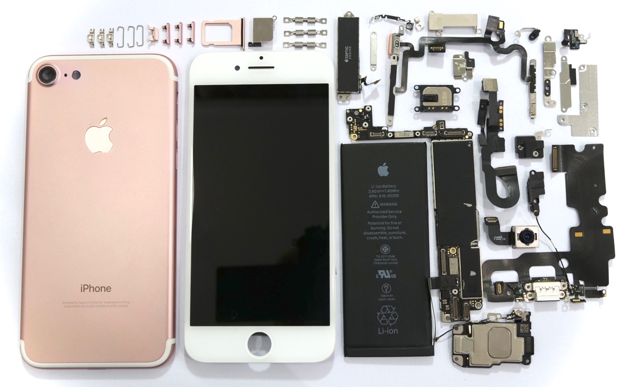
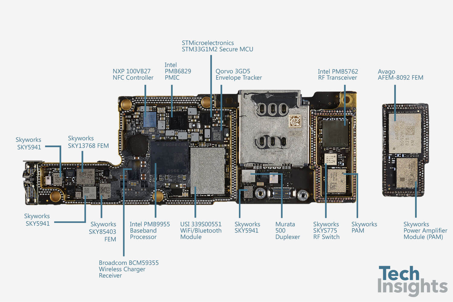
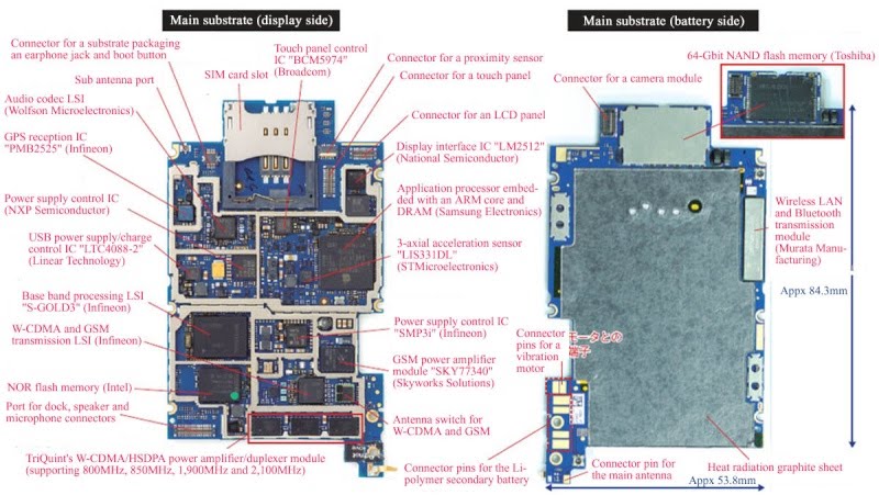
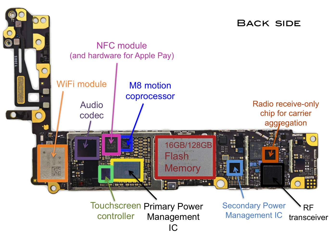
iPhone Schematic Diagram: A journey into the heart of Apple’s iconic device. It’s not just a collection of lines and symbols, but a blueprint of innovation, a testament to the meticulous engineering that makes the iPhone tick. This schematic diagram acts as a guide, unveiling the intricate web of components and subsystems that orchestrate the seamless user experience we’ve come to expect.
Imagine peering inside the iPhone, not just to see the physical components, but to understand how they interact and function. That’s the power of a schematic diagram. It’s a visual language that translates the complex workings of the iPhone into a comprehensible form, revealing the hidden symphony of technology that powers our digital lives.
Key Components and Subsystems

The iPhone’s functionality relies on a complex interplay of hardware and software components, each contributing to the overall user experience. These components work together seamlessly to enable communication, processing, display, and storage of information.
Key Components and Subsystems
The iPhone’s functionality relies on a complex interplay of hardware and software components, each contributing to the overall user experience. These components work together seamlessly to enable communication, processing, display, and storage of information.
| Component Name | Description | Function | Schematic Representation |
|---|---|---|---|
| Processor (CPU) | The brain of the iPhone, responsible for executing instructions and performing calculations. | Processes data, runs applications, and manages the overall operation of the device. | [Schematic representation of a CPU] |
| Memory (RAM) | Temporary storage for data and instructions that the CPU is currently using. | Stores data that is actively being used by the CPU, enabling fast access and processing. | [Schematic representation of RAM] |
| Storage (Flash Memory) | Permanent storage for data, applications, and operating system files. | Stores data and files persistently, even when the device is powered off. | [Schematic representation of Flash Memory] |
| Display (LCD or OLED) | Visual interface for interacting with the iPhone. | Displays information, images, and videos, enabling user interaction with the device. | [Schematic representation of a display] |
| Battery | Power source for the iPhone. | Provides energy to operate the device and its components. | [Schematic representation of a battery] |
| Camera | Optical sensor that captures images and videos. | Enables users to take photos and record videos. | [Schematic representation of a camera] |
| Sensors (Accelerometer, Gyroscope, Compass) | Devices that detect changes in motion, orientation, and magnetic fields. | Provide information about the device’s position, movement, and direction. | [Schematic representation of sensors] |
| Cellular Modem | Enables communication over cellular networks. | Connects the iPhone to cellular networks for voice calls, data transmission, and other services. | [Schematic representation of a cellular modem] |
| Wi-Fi Module | Enables communication over Wi-Fi networks. | Connects the iPhone to Wi-Fi networks for internet access and other services. | [Schematic representation of a Wi-Fi module] |
| Bluetooth Module | Enables wireless communication with other Bluetooth-enabled devices. | Connects the iPhone to Bluetooth devices such as headphones, speakers, and other peripherals. | [Schematic representation of a Bluetooth module] |
| GPS Receiver | Determines the iPhone’s location using satellite signals. | Provides location data for navigation, mapping, and other location-based services. | [Schematic representation of a GPS receiver] |
| Audio Amplifier | Amplifies audio signals for speakers and headphones. | Enables the iPhone to produce sound for calls, music, and other audio content. | [Schematic representation of an audio amplifier] |
| Microphone | Captures audio signals for voice calls, recordings, and voice assistants. | Enables users to record audio and communicate through voice calls. | [Schematic representation of a microphone] |
Interconnections and Interactions
The components and subsystems within the iPhone are interconnected through a complex network of circuits and buses. These interconnections allow for data exchange and communication between different parts of the device. For instance, the CPU communicates with RAM to access data, the display receives signals from the CPU to render images, and the camera transmits captured images to the CPU for processing.
Role of Components in Overall Functionality
Each component plays a crucial role in the overall functionality of the iPhone. The processor executes instructions and performs calculations, while the memory provides temporary storage for data and instructions. The storage permanently stores data and applications, and the display enables user interaction with the device. The battery provides power, the camera captures images and videos, and the sensors provide information about the device’s position and movement.
The iPhone schematic diagram, a blueprint of its intricate inner workings, reveals a complex network of components. It’s fascinating to trace the flow of data, the interplay of circuits, and the delicate balance of power that brings the device to life. But even the most detailed schematic can’t capture the vibrant personality that a user infuses into their phone. Perhaps that’s why many choose to personalize their device with a visually striking wallpaper, like the stunning one piece wallpaper iphone 4k that brings the world of anime to their screen.
This wallpaper, a testament to individual taste, overlays the technical diagram with a layer of personal expression, highlighting the iPhone’s potential to transcend its functional purpose and become a reflection of its owner’s identity.
The cellular modem, Wi-Fi module, and Bluetooth module enable communication with other devices, while the GPS receiver provides location data. The audio amplifier amplifies sound, and the microphone captures audio signals.
Schematic Diagram Interpretation

Schematic diagrams are essential tools for understanding the internal workings of an iPhone. They provide a visual representation of the device’s components, their connections, and how data flows between them. This section explores the conventions used in iPhone schematic diagrams and explains how to interpret the information presented.
Conventions and Symbols
Schematic diagrams use standardized symbols to represent various electronic components. Understanding these symbols is crucial for interpreting the diagram accurately. Some common symbols include:
- Resistors: A zig-zag line represents a resistor, a component that restricts the flow of electricity.
- Capacitors: Two parallel lines represent a capacitor, a component that stores electrical energy.
- Inductors: A coil shape represents an inductor, a component that opposes changes in current flow.
- Transistors: A triangle with a line connected to its base represents a transistor, a component that acts as a switch or amplifier.
- Diodes: A triangle with a line connected to its tip represents a diode, a component that allows current flow in only one direction.
Interpreting Connections
Schematic diagrams show the connections between components using lines. These lines represent wires or traces on the circuit board. The thickness of the line can indicate the size of the wire, which can be related to the amount of current flowing through it.
- Connections: Lines connecting two components indicate that they are electrically connected. The connection points are typically marked with a dot or a junction symbol.
- Ground: A line with a symbol resembling the earth represents a ground connection, which is a common reference point for electrical circuits.
- Power: Lines labeled with a “V” or “+” symbol indicate a power supply connection.
Understanding Signal Flow and Data Transmission
Schematic diagrams also show the flow of signals and data through the device. These signals can be electrical, optical, or wireless. The direction of the signal flow is often indicated by arrows on the lines.
- Signal Direction: Arrows on lines indicate the direction of signal flow. For example, an arrow pointing from a microphone to an amplifier indicates that the microphone sends audio signals to the amplifier.
- Data Buses: Multiple lines grouped together can represent a data bus, which is a set of wires used to transmit data between components. The width of the bus indicates the number of data bits that can be transmitted simultaneously.
Analyzing Power Distribution and Circuitry
Schematic diagrams provide insights into the power distribution system and circuitry within the iPhone. The power supply components, such as batteries, regulators, and converters, are represented, along with their connections to the rest of the device.
- Power Supply: Components like batteries, power regulators, and converters are shown in the schematic, illustrating how power is supplied to the device.
- Circuitry: The arrangement of components and their connections form various circuits. The schematic reveals how these circuits function to control and manage power flow.
Troubleshooting Common iPhone Problems
Schematic diagrams are valuable tools for troubleshooting common iPhone problems. By analyzing the diagram, you can identify the potential cause of a problem and trace the signal flow to determine where the issue might be located.
- No Power: If an iPhone does not turn on, a schematic diagram can help identify potential causes, such as a faulty battery, a problem with the power regulator, or a broken connection in the power supply circuit.
- Audio Issues: A schematic diagram can help pinpoint the source of audio problems, such as a faulty microphone, a malfunctioning speaker, or a broken connection in the audio signal path.
- Display Problems: A schematic diagram can help identify the cause of display problems, such as a faulty display driver, a broken connection in the display data bus, or a malfunctioning display panel.
Evolution of iPhone Schematic Diagrams

The evolution of iPhone schematic diagrams reflects the rapid advancements in mobile technology and the constant pursuit of innovation by Apple. These diagrams, which depict the intricate internal workings of iPhones, have become increasingly complex and sophisticated over time, mirroring the growing number of components and the integration of new technologies.
Evolution of iPhone Schematic Diagrams
The schematic diagrams of iPhones have undergone significant changes over the years, reflecting the continuous evolution of the device’s hardware and software. These changes are evident in the addition of new components, the refinement of existing ones, and the overall complexity of the diagrams.
- Early iPhones: The schematic diagrams of early iPhones, such as the iPhone 1 and iPhone 3G, were relatively simple, showcasing a limited number of components and a straightforward architecture. These diagrams highlighted key components like the display, processor, memory, and battery, providing a basic understanding of the device’s structure.
- Introduction of New Technologies: With the introduction of new technologies like the Retina display, multi-core processors, and advanced cameras, iPhone schematic diagrams became more intricate. The iPhone 4 and iPhone 5 models, for instance, showcased the integration of these new technologies, resulting in more complex diagrams with a greater number of components and interconnections.
- Increasing Complexity: The advent of the iPhone 6 and subsequent models, with their larger displays, powerful processors, and enhanced features, further escalated the complexity of iPhone schematic diagrams. The inclusion of components like NFC, barometers, and gyroscopes, along with the integration of new technologies like Apple Pay and 3D Touch, resulted in highly detailed diagrams with intricate interconnections.
- Evolution of Existing Components: Existing components have also undergone significant evolution, reflected in the schematic diagrams. For example, the evolution of the A-series processors, from the single-core A4 chip in the iPhone 4 to the powerful multi-core A16 Bionic chip in the iPhone 14 Pro, is evident in the diagrams, showcasing the increasing complexity and capabilities of these processors.
Impact of Technological Advancements
Technological advancements have had a profound impact on the complexity and sophistication of iPhone schematic diagrams. The introduction of new technologies, the miniaturization of components, and the increasing integration of hardware and software have resulted in highly intricate diagrams that capture the intricate workings of modern iPhones.
The evolution of iPhone schematic diagrams is a testament to the rapid pace of technological advancement and the constant drive to innovate. These diagrams provide a fascinating glimpse into the inner workings of these ubiquitous devices and highlight the remarkable engineering feats that have made them possible.
Applications of iPhone Schematic Diagrams

iPhone schematic diagrams are invaluable tools that extend beyond simply illustrating the internal components of an iPhone. They serve as blueprints for various applications, guiding product development, manufacturing, repair, and even education.
The comprehensive nature of iPhone schematic diagrams, which depict the intricate connections between components, provides valuable insights for various stakeholders. These diagrams are instrumental in understanding the functionality of the device, aiding in its creation, maintenance, and even the exploration of its design principles.
Product Design and Development
iPhone schematic diagrams play a crucial role in the iterative process of product design and development. Engineers use these diagrams to visualize and refine the layout of components, ensuring optimal functionality and efficiency. They also help in the selection of appropriate components, considering factors like size, power consumption, and compatibility.
For example, during the development of the iPhone X, engineers used schematic diagrams to analyze the placement of the OLED display, the Face ID sensor, and the wireless charging coil.
By studying the interconnections between these components, they were able to optimize the design for performance and user experience.
Manufacturing and Assembly
Schematic diagrams are essential for guiding the manufacturing and assembly process of iPhones. They provide clear instructions for assembling the device, ensuring that components are connected correctly and in the proper order. The diagrams also help in identifying the tools and equipment required for each step of the assembly process.
In iPhone manufacturing facilities, workers rely on schematic diagrams to accurately assemble components like the motherboard, display, and battery.
The diagrams serve as visual guides, minimizing errors and ensuring consistency in the production process.
Repair and Maintenance
iPhone schematic diagrams are indispensable tools for technicians involved in repairing and maintaining iPhones. These diagrams allow technicians to identify specific components, understand their functions, and troubleshoot issues effectively. They also provide guidance on how to safely disassemble and reassemble the device.
For instance, a technician repairing a damaged iPhone screen can use a schematic diagram to locate the specific connectors and cables responsible for transmitting data and power to the display.
The diagram also guides the technician in removing and replacing the screen without damaging other components.
Reverse Engineering
iPhone schematic diagrams can be used for reverse engineering, a process of analyzing a device to understand its design and functionality. By studying the interconnections between components, engineers can gain insights into the device’s architecture and design principles. This information can be used to develop compatible accessories or to create alternative designs.
For example, a company developing a third-party iPhone case might use a schematic diagram to understand the placement of buttons, ports, and other features.
This information would help them design a case that fits perfectly and allows access to all essential functions.
Education and Training, Iphone schematic diagram
iPhone schematic diagrams are valuable educational tools for students and professionals interested in learning about electronics and mobile device technology. They provide a visual representation of the internal workings of an iPhone, allowing users to understand the relationships between components and their functions.
Educational institutions use iPhone schematic diagrams to teach students about the principles of electronics, circuit design, and mobile device architecture.
These diagrams help students visualize the complex interactions between components and gain a deeper understanding of how iPhones function.
Q&A
Where can I find iPhone schematic diagrams?
You can find iPhone schematic diagrams in official Apple documentation, online databases, and technical forums. However, be mindful of copyright restrictions and ensure you’re accessing legitimate resources.
Are there any tools for creating or viewing iPhone schematic diagrams?
Yes, several software tools are available for creating and viewing schematic diagrams. Some popular options include Eagle, KiCad, and Altium Designer. These tools offer a range of features, including component libraries, circuit simulation, and layout design.
What is the difference between a block diagram and an electrical schematic?
A block diagram provides a high-level overview of the system, showing the major components and their connections. An electrical schematic, on the other hand, depicts the detailed wiring and circuitry, including specific components and their interconnections.